
BOM
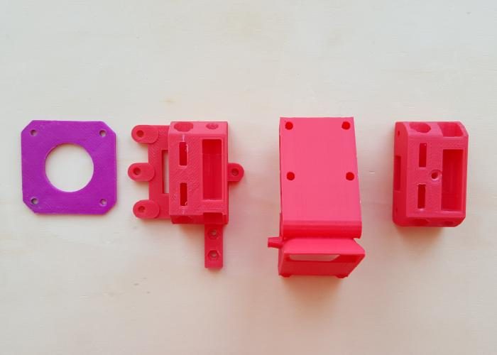
Printed parts
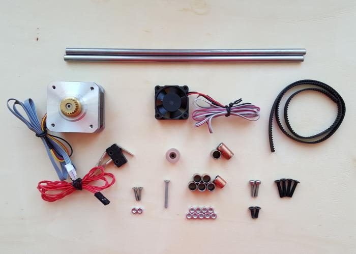
Other material
Tools
Directions
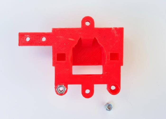
X-motor
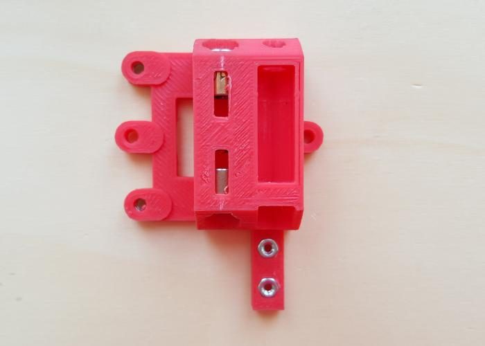
Insert 2 M3 nuts in the respective holes (bottom side).
Prepare the x-motor printed part, the 2 12mm M2.5 screws and 2 M2.5 nuts.
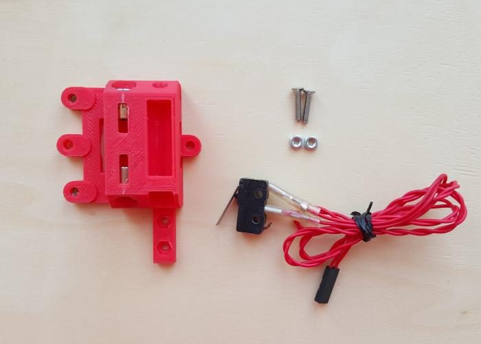
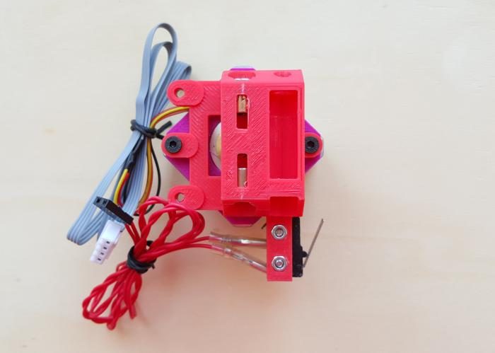
Insert the 2 M2.5 nuts in place, the endstop place.
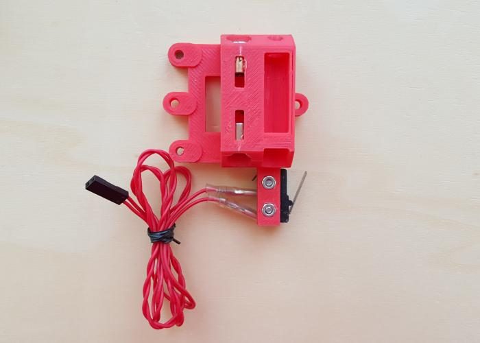
Attach the endstop with 2 12 mm M2.5 screws.
Take the motor, 2 10mm M3 screws.
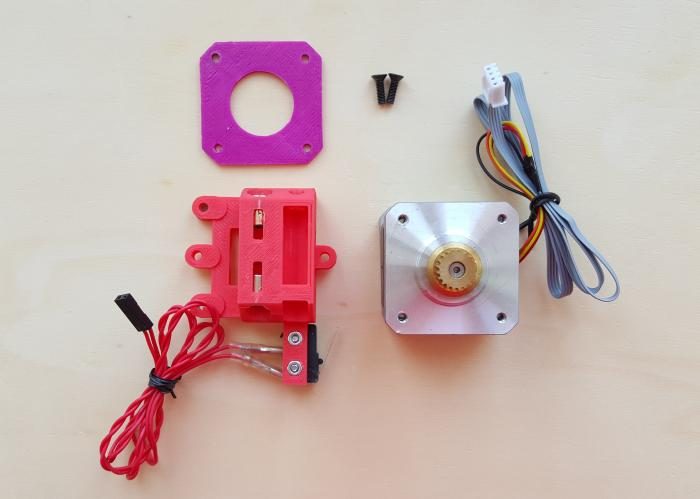
Place the spacer on the motor.
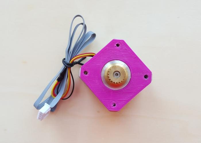
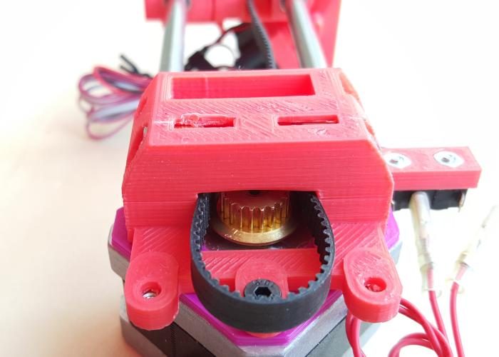
Attach motor as in picture, with 2 10 mm M3 screws. Note that the motor wire should be placed SW.
X-bearing/idler assembly
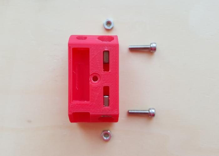
Prepare the necessary material to assembly the x-bearing.
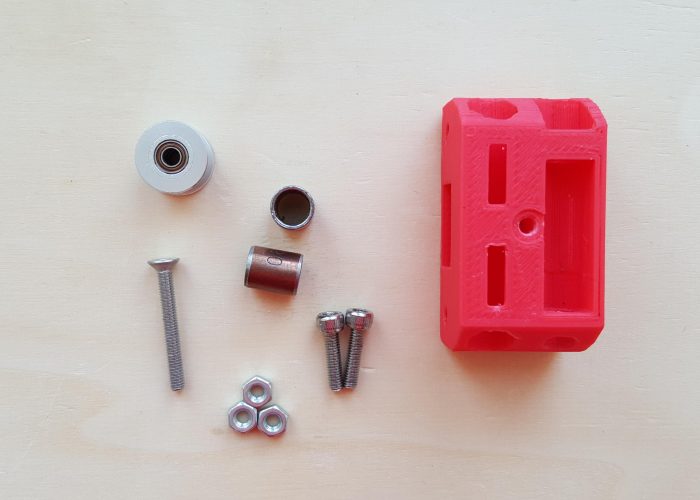
Insert two bushings in place, as in figure.
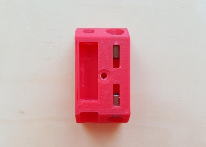
Insert 2 M3 nuts in place, the tensioner place. Screw the 2 10 mm M3 nuts, just enough to hold the nuts. These will be used later to adjust the tension in the belt.
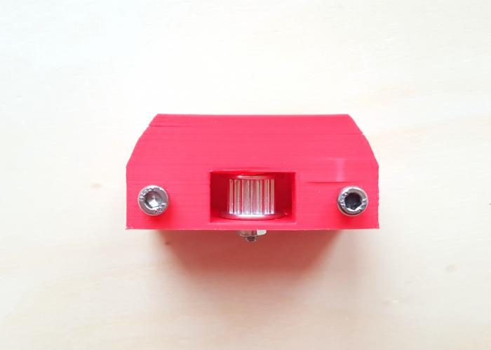
Insert the pulley/bearing inside the printed part. Use the 25 mm screw and ...
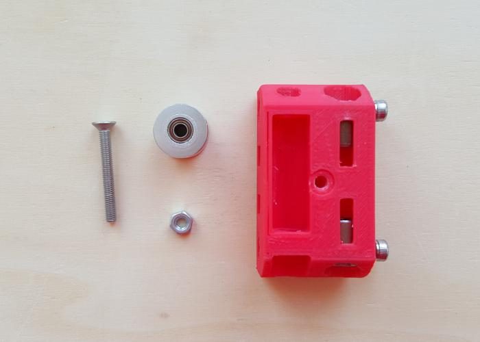
... the M3 nut to attach it.
X-carriage
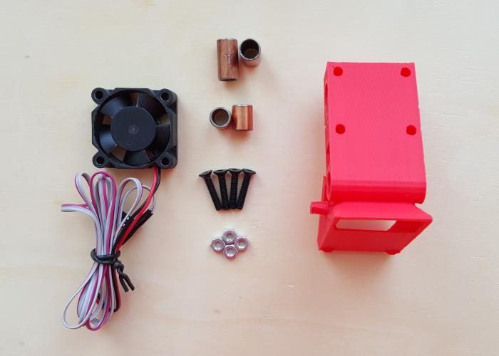
Prepare the carriage, fan, bushings, 20mm M3 screws and 4 M3 nuts.
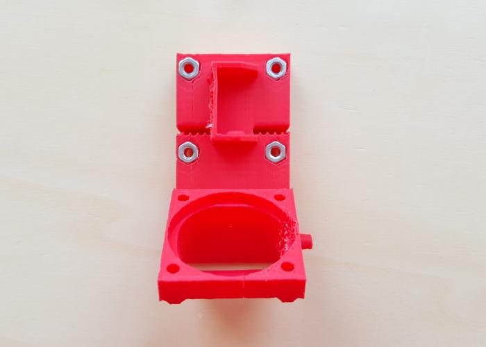
Insert the 4 bushings in the indicated place.
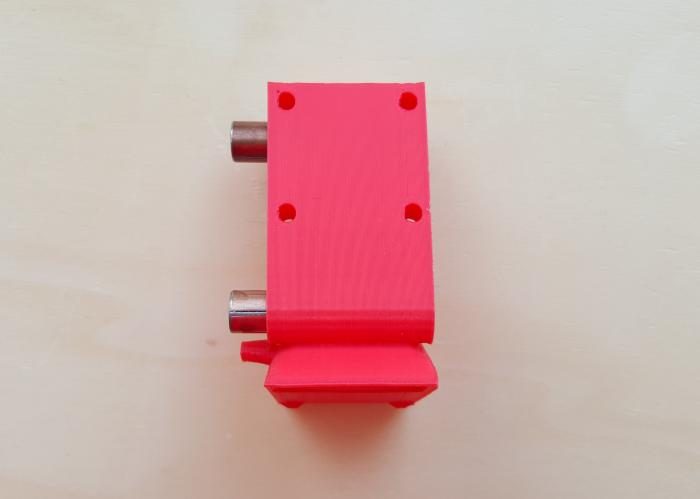
Insert 4 M3 nuts in the back side of the carriage printed part. Note: If necessary, you can use an M3 screw to insert and hold the nut in place.
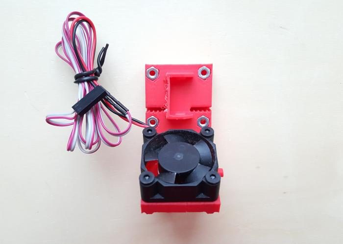
Prepare the fan, 2 M2.5 nuts and 4 M2.5 nuts.
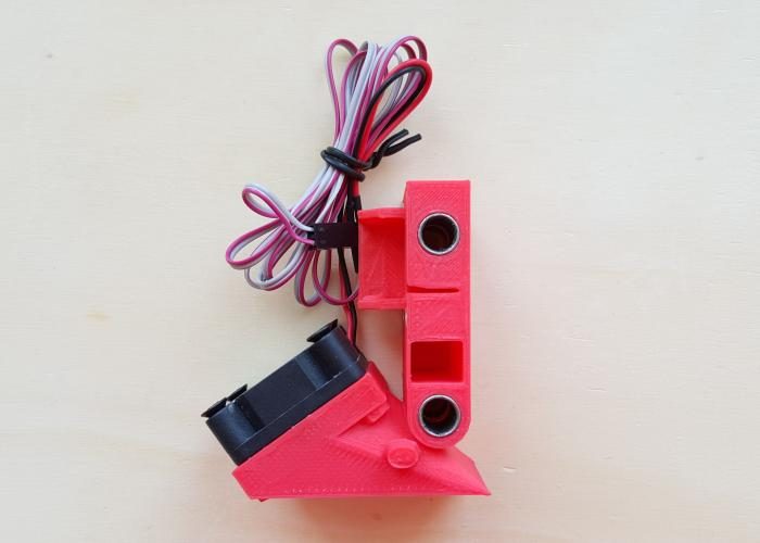
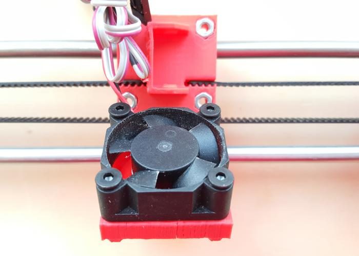
Attach the fan to the carriage. Use 4 16 mm M2.5 screws. The inside screws ate attached to the plastic and the outside ones are attached to 2 M2.5 nuts. Note that the fan wires should be left on the side, this facilitates the insertion into the cable chain, later.
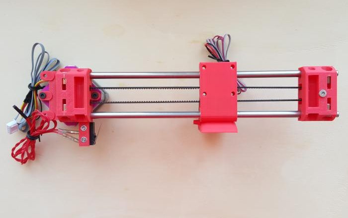
X-axis assembly
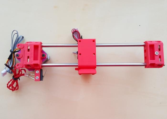
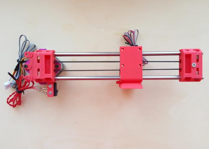
Take the 2 221mm smooth rods and insert them into the bushings, in the carriage.
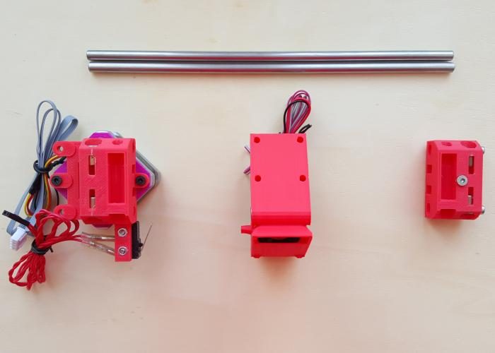
Insert he rods (now with the carriage) in the X-motor part on one side. Next, insert the rods in the X-idle-bearing.
Take the 440 mm GT2 belt.
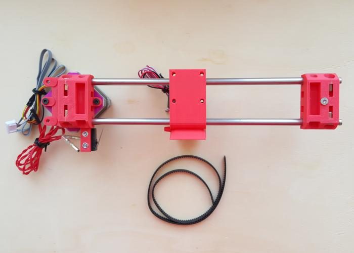
Insert it in the teeth hole in the carriage hole, in the back. Guide it through the x-bearing part, over the bearing. Guide it through the carriage...
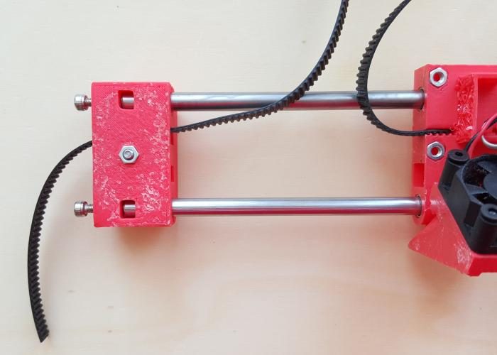
and pass the other loose tip over the x-motor pulley.
Then, back to the carriage, insert the belt in the teeth hole, in the back.
Try to apply some tension to the belt. It should not be too loose, but also not so tight that the motor cannot move freely and smoothly.
BOM (Bill Of Materials)
Printed parts
Other material
Tools
Directions
X-motor
Insert 2 M3 nuts in the respective holes (bottom side).
Prepare the x-motor printed part, the 2 12mm M2.5 screws and 2 M2.5 nuts.
Insert the 2 M2.5 nuts in place, the endstop place.
Attach the endstop with 2 12 mm M2.5 screws.
Take the motor, 2 10mm M3 screws.
Place the spacer on the motor.
Attach motor as in picture, with 2 10 mm M3 screws. Note that the motor wire should be placed SW.
X-bearing/idler assembly
Prepare the necessary material to assembly the x-bearing.
Insert two bushings in place, as in figure.
Insert 2 M3 nuts in place, the tensioner place. Screw the 2 10 mm M3 nuts, just enough to hold the nuts. These will be used later to adjust the tension in the belt.
Insert the pulley/bearing inside the printed part. Use the 25 mm screw and ...
... the M3 nut to attach it.
X-carriage
Prepare the carriage, fan, bushings, 20mm M3 screws and 4 M3 nuts.
Insert the 4 bushings in the indicated place.
Insert 4 M3 nuts in the back side of the carriage printed part. Note: If necessary, you can use an M3 screw to insert and hold the nut in place.
Prepare the fan, 2 M2.5 nuts and 4 M2.5 nuts.
Attach the fan to the carriage. Use 4 16 mm M2.5 screws. The inside screws ate attached to the plastic and the outside ones are attached to 2 M2.5 nuts. Note that the fan wires should be left on the side, this facilitates the insertion into the cable chain, later.
X-axis assembly
Take the 2 221mm smooth rods and insert them into the bushings, in the carriage.
Insert he rods (now with the carriage) in the X-motor part on one side. Next, insert the rods in the X-idle-bearing.
Take the 440 mm GT2 belt.
Insert it in the teeth hole in the carriage hole, in the back. Guide it through the x-bearing part, over the bearing. Guide it through the carriage...
and pass the other loose tip over the x-motor pulley.
Then, back to the carriage, insert the belt in the teeth hole, in the back.
Try to apply some tension to the belt. It should not be too loose, but also not so tight that the motor cannot move freely and smoothly.