
BOM (Bill Of Materials)
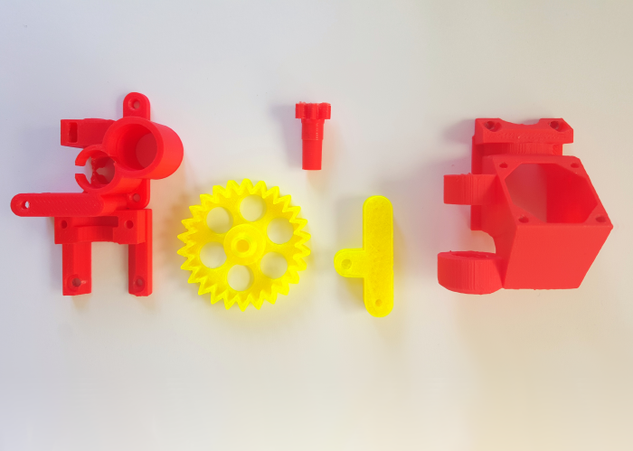
Printed parts
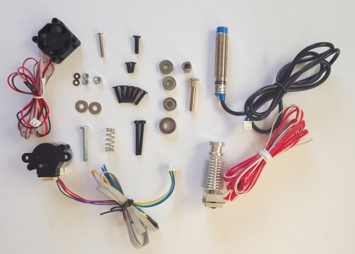
Other parts
Directions
Extruder assembly
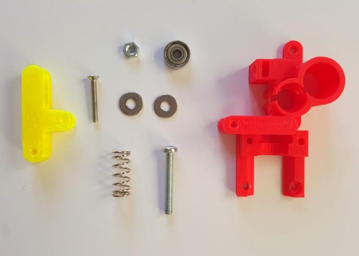
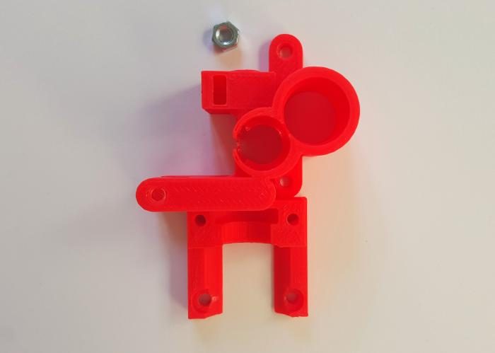
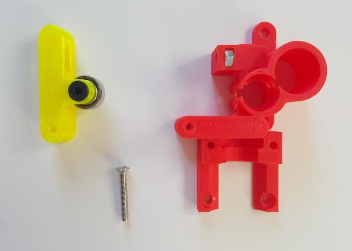
Take the extruder printed parts and some of the material as presented in the picture below.
Take the M4 nut.
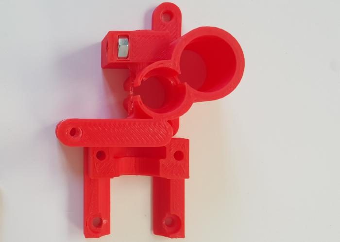
Insert the M4 nut in place.
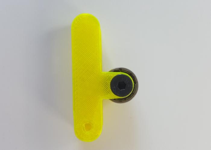
Insert the 694zz bearing in the tensioner arm printed part.
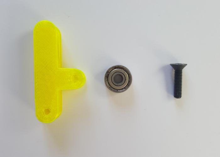
Secure the bearing with the M4 16 mm Allen screw.
Attach the arm to the main part, use the M3 20 mm Allen screw.
Prepare the tensioner.
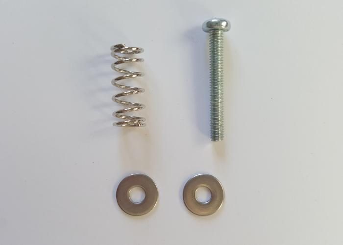
Mount the screw, washers and spring, as in the picture.
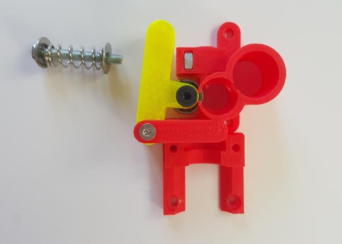
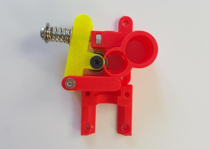
Screw the tensioner to the extruder.
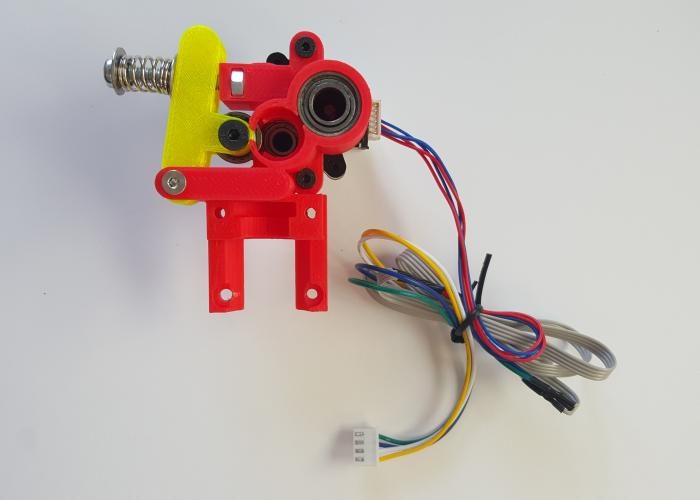
Take the 688zz and the remaining 695zz bearings.
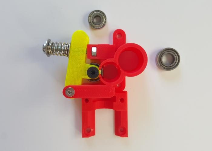
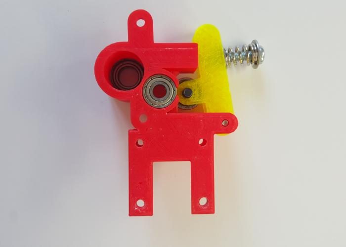
Insert the 688zz bearing from above, in the extruder.
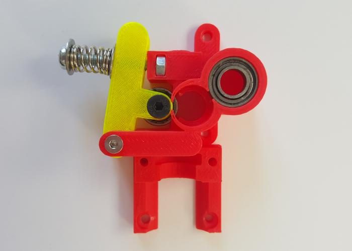
Insert the 695zz bearing from below, in the extruder.
Prepare the motor, 2 10mm Allen screws, two lock washers and two nuts.
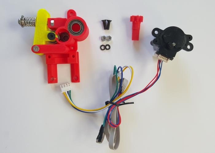
Attach the motor as presented in the pictures below.
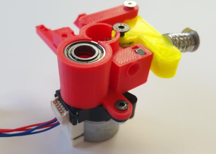
Take the small wheel and insert it, carefully, through the 688zz bearing and into the motor shaft.
Take 2 16mm M3 screws.
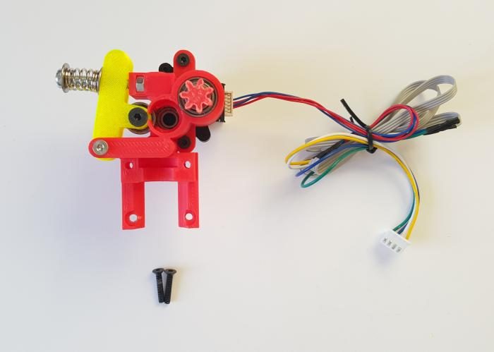
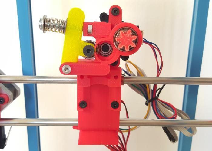
Attach the extruder to the carriage.
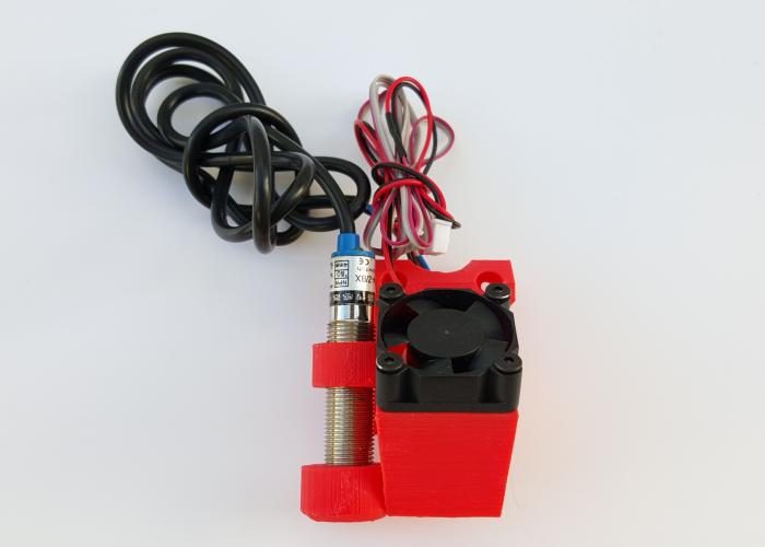
Z probe and fan mount
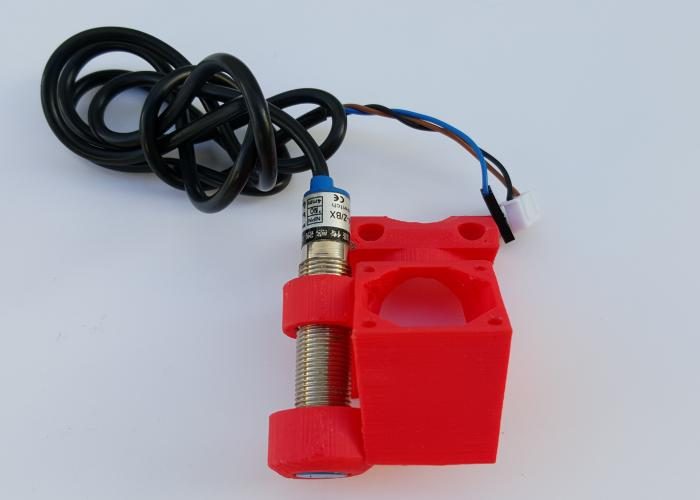
Take the Z probe and the printed part and ...
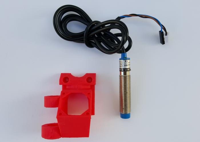
... screw the Z probe in the respective hole.
Take the part, the fan, the 4 16mm screws and...
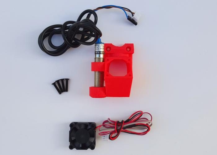
... assembly the fan. Make sure the fan wire stays on top.
Mount the nozzle in the extruder, as in the picture.
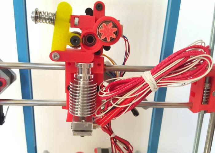
Take the 2 30mm screws and the mounted part.
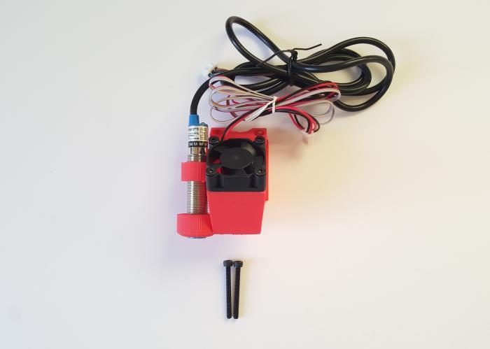
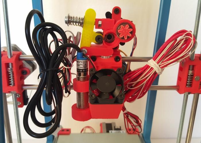
Attach the front part to the extruder-carriage.
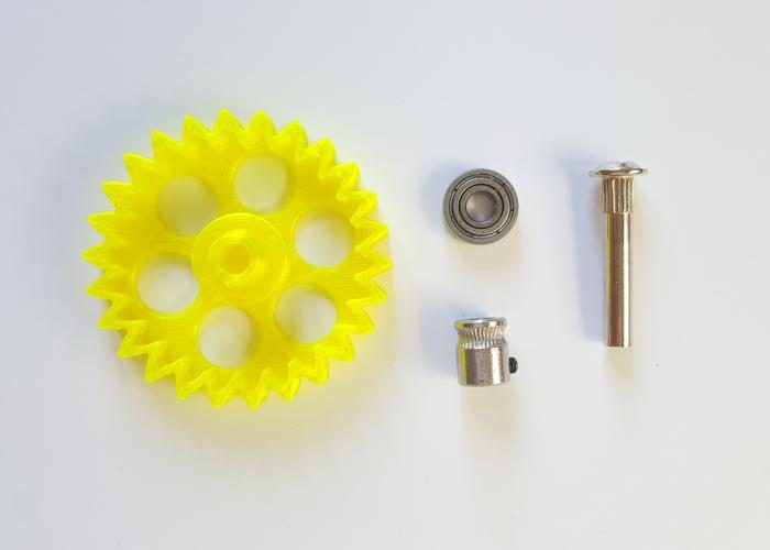
Wheel - MK8 assembly
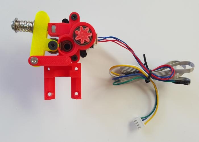
Now we are going to prepare another central piece of the extruder - the gear-wheel that allows the filament to be pushed/pulled to/from the nozzle.
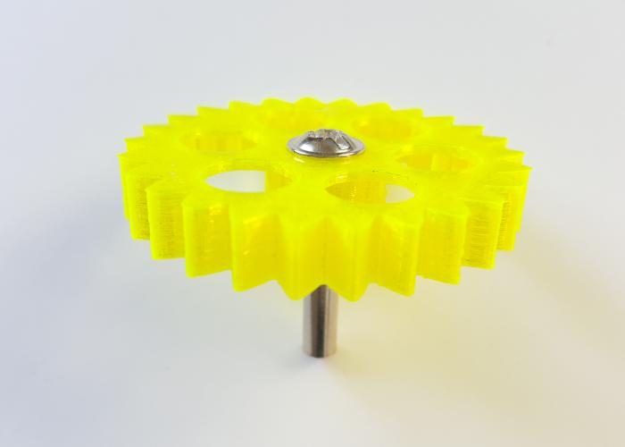
Insert the hex M5 bolt in the bigger wheel.
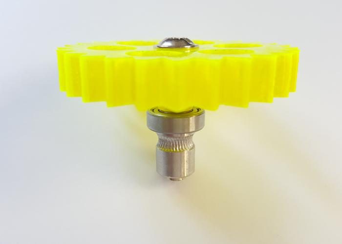
Insert the 695 bearing and the hobbed gear as in the picture.
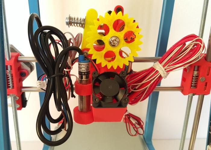
Insert the wheel into the assembled extruder.
BOM (Bill Of Materials)
Printed parts
Other parts
Directions
Extruder assembly
Take the extruder printed parts and some of the material as presented in the picture below.
Take the M4 nut.
Insert the M4 nut in place.
Insert the 694zz bearing in the tensioner arm printed part.
Secure the bearing with the M4 16 mm Allen screw.
Attach the arm to the main part, use the M3 20 mm Allen screw.
Prepare the tensioner.
Mount the screw, washers and spring, as in the picture.
Screw the tensioner to the extruder.
Take the 688zz and the remaining 695zz bearings.
Insert the 688zz bearing from above, in the extruder.
Insert the 695zz bearing from below, in the extruder.
Prepare the motor, 2 10mm Allen screws, two lock washers and two nuts.
Attach the motor as presented in the pictures below.
Take the small wheel and insert it, carefully, through the 688zz bearing and into the motor shaft.
Take 2 16mm M3 screws.
Attach the extruder to the carriage.
Z probe and fan mount
Take the Z probe and the printed part and ...
... screw the Z probe in the respective hole.
Take the part, the fan, the 4 16mm screws and...
... assembly the fan. Make sure the fan wire stays on top.
Mount the nozzle in the extruder, as in the picture.
Take the 2 30mm screws and the mounted part.
Attach the front part to the extruder-carriage.
Wheel - MK8 assembly
Now we are going to prepare another central piece of the extruder - the gear-wheel that allows the filament to be pushed/pulled to/from the nozzle.
Insert the hex M5 bolt in the bigger wheel.
Insert the 695 bearing and the hobbed gear as in the picture.
Insert the wheel into the assembled extruder.